Aluminum 1100
Nominal Chemical
Composition
INTRODUCTION
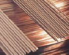
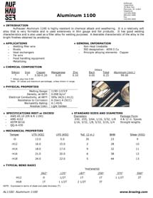
Aufhauser Aluminum 1100 is highly resistant to chemical attack and weathering. It is a relatively soft alloy that is very formable and is used extensively in thin gauge and foil products. It has good welding characteristics and is also used as a filler alloy for welding purposes. A desirable characteristic of the alloy is the bright finishes obtained by anodizing.
APPLICATIONS
- Welding filler wire
- Rivets
- Heat exchangers
- Tie wire
- Food handling equipment
- Metallizing
GENERAL INFORMATION
- Non-Heat treatable
- Principle alloying elements: Copper
- ISO designation: AI99.0 Cu
Chemical Composition
| Silicon | Iron | Copper | Manganese | Zinc | Each | Total Others |
Aluminum |
|---|---|---|---|---|---|---|---|
| * | * | 0.05-0.20 | 0.05 | 0.10 | 0.05 | 0.15 | 99.0 |
* Silicon + Iron = 0.95% max.
PHYSICAL and MECHANICAL PROPERTIES
| Melting Range | 1190-1215°F (643-657°C) |
| Density at 68°F | 0.098 lbs./in³ |
| Conductivity at 68°F | 59% IACS (-H12) |
| Resistance to Corrosion | A (Gen) A (SCC) |
| Workability Rating | A (-H14) |
| Anodize Color | Light Golden |
SPECIFICATIONS MEET OR EXCEED
| AWS A5.10 (ER & R 1100) |
| AMS 4102 |
| ASTM B316 |
| QQ-A-430 |
TYPICAL THERMAL TREATMENT
| Metal Temp. | Temper | |
|---|---|---|
| Annealing Practice | 650°F | -O |
MECHANICAL PROPERTIES
| Temper | UTS (KSI) | UYS (KSI) | %E (2 in) | BHN | Shear (KSI) |
|---|---|---|---|---|---|
| -O | 13.0 | 5.0 | 35 | 23 | 9 |
| -H12 | 16.0 | 15.0 | 2 | 28 | 10 |
| -H14 | 18.0 | 17.0 | 9 | 32 | 11 |
| -H16 | 21.0 | 20.0 | 6 | 38 | 12 |
| -H18 | 24.0 | 22.0 | 5 | 44 | 13 |
TYPICAL BEND RADII
THICKNESS (INCHES) |
||||||
| 0.062 | 0.125 | 0.187 | 0.250 | 0.375 | 0.500 | |
|---|---|---|---|---|---|---|
| -H12 | 0 | 1/2T | 1T | 1T | 1 1/2T | 2T |
| -H18 | 1T | 1 1/2T | 2 1/2T | 3T | ||
Note: Expressed in terms of sheet and plate thickness (T).
STANDARD SIZES AND DIAMETERS
| Diameters (inches) | Package Form |
|---|---|
| 0.030, 0.035, 3/64, 1/16, 3/32, 1/8 | 4 & 12 in. Spools |
| 1/16, 3/32, 1/8, 5/32, 3/16, 1/4 | Straight lengths |
TYPICAL GMAW PARAMETERS
| Wire diameter | Range | Base material thickness | Suggested | Wire feed | Gas flow | Consumption 100 ft of weld |
||
|---|---|---|---|---|---|---|---|---|
| INCHES | AMPS | VOLTS | INCHES | AMPS |
VOLTS |
IPM |
CFH | POUNDS |
| 0.030 | 60-170 | 13-24 | 0.062 | 90 | 22 | 260 | 25 | 1.5 |
| 0.094 | 110 | 23 | 320 | 1.8 | ||||
| 0.125 | 130 | 23 | 380 | 2 | ||||
| 0.187 | 150 | 24 | 430 | 4 | ||||
| 0.250 | 175 | 24 | 510 | 6 | ||||
| 0.035 | 70-180 | 15-26 | 0.062 | 90 | 23 | 250 | 35 | 1.5 |
| 0.125 | 130 | 24 | 360 | 2 | ||||
| 0.250 | 170 | 25 | 470 | 6 | ||||
| 0.047 | 140-260 | 20-29 | 0.094 | 110 | 25 | 215 | 45 | 1.8 |
| 0.125 | 150 | 26 | 370 | 2 | ||||
| 0.250 | 190 | 26 | 370 | 6 | ||||
| 0.375 | 220 | 27 | 430 | 16 | ||||
| 0.062 | 190-350 | 25-30 | 0.250 | 200 | 26 | 190 | 55 | 6 |
| 0.375 | 230 | 27 | 215 | 16 | ||||
| 0.500 | 260 | 28 | 240 | 30 | ||||
| 0.750 | 280 | 29 | 261 | 50 | ||||
| 1.000 | 300 | 30 | 280 | 105 | ||||
| 0.094 | 280-400 | 26-31 | 0.500 | 280 | 28 | 170 | 65 | 30 |
| 0.750 | 290 | 29 | 175 | 50 | ||||
| >1.000 | 300 | 30 | 180 | 150+ | ||||
NOTE: Parameters based on flat position, groove joint, backing strip, and 100% argon gas.


